- cut_line_paramsCutting line parameters, which are a, b, and c in line equation a*x+b*y+c=0. Note that a*x+b*y+c>0 part is being removed.
C++ Type:std::vector<double>
Unit:(no unit assumed)
Controllable:No
Description:Cutting line parameters, which are a, b, and c in line equation a*x+b*y+c=0. Note that a*x+b*y+c>0 part is being removed.
- inputThe input mesh that needs to be trimmed.
C++ Type:MeshGeneratorName
Controllable:No
Description:The input mesh that needs to be trimmed.
- new_boundary_idBoundary id to be assigned to the boundary formed by the cutting.
C++ Type:short
Controllable:No
Description:Boundary id to be assigned to the boundary formed by the cutting.
XYMeshLineCutter
This XYMeshLineCutter object is designed to trim the input mesh by removing all the elements on one side of a given straight line with special processing on the elements crossed by the cutting line to ensure a smooth cross-section.
Overview
The XYMeshLineCutter is used to trim off a fraction of the input mesh which is located on one side of a given straight line. The input mesh, which is given by "input", must be a 2D mesh in the XY-plane and only contain TRI3 and QUAD4 elements. The cutting straight line is provided by "cut_line_params", which is a vector of three Real type values, which are , , and in the line equation . This mesh generator remove the part of the mesh that matches . The trimmed mesh is processed to ensure a smooth cross-section instead of a "zigzag" cross-section as generated by PlaneDeletionGenerator.
Two methods can be used by this mesh generator to achieve the mesh cutting: the "Element Cutting" (CUT_ELEM_TRI) method and the "Node Moving" (MOV_NODE) method, which can be selected through "cutting_type". The MOV_NODE method is the same method used by HexagonMeshTrimmer and CartesianMeshTrimmer in the Reactor module. That is, the nodes near the cutting line are moved to the cutting line to ensure the smoothness of the cross-section. On the other hand, the CUT_ELEM_TRI method first converts all the QUAD4 elements crossed by the cutting line into pairs of TRI3 elements. Then all the TRI3 elements crossed by the cutting line are further split into two or three TRI elements with a division matching the cutting line.
The two methods have their own Cons and Pros, respectively, and are complementary to each other. The CUT_ELEM_TRI method keeps all the subdomain interfaces and even preserves the volume of the subdomains. However, it may lead to some small elements near the cutting line. On the other hand, the MOV_NODE method does not produce too fine elements but may deform the subdomain interfaces, hence not preserving relative subdomain volumes. Therefore, if only one subdomain is involved in the cutting, or all the cut subdomain interfaces are symmetric over the cutting line, the MOV_NODE method is preferred. On the other hand, if complex subdomain interfaces are involved in the cutting, the CUT_ELEM_TRI method is preferred.
The id of the new external boundary produced by the trimming can be assigned using "new_boundary_id". As either method creates TRI3 elements if there are QUAD4 elements crossed by the cutting line, and as Exodus format does not allow TRI3 and QUAD4 elements sharing the same subdomain id and name. The newly formed TRI3 subdomains' ids and names can be customized using "tri_elem_subdomain_name_suffix" and "tri_elem_subdomain_shift".
Example Syntax
The simple example of this mesh generator is to cut a square mesh that contains only one subdomain as shown in Figure 1.
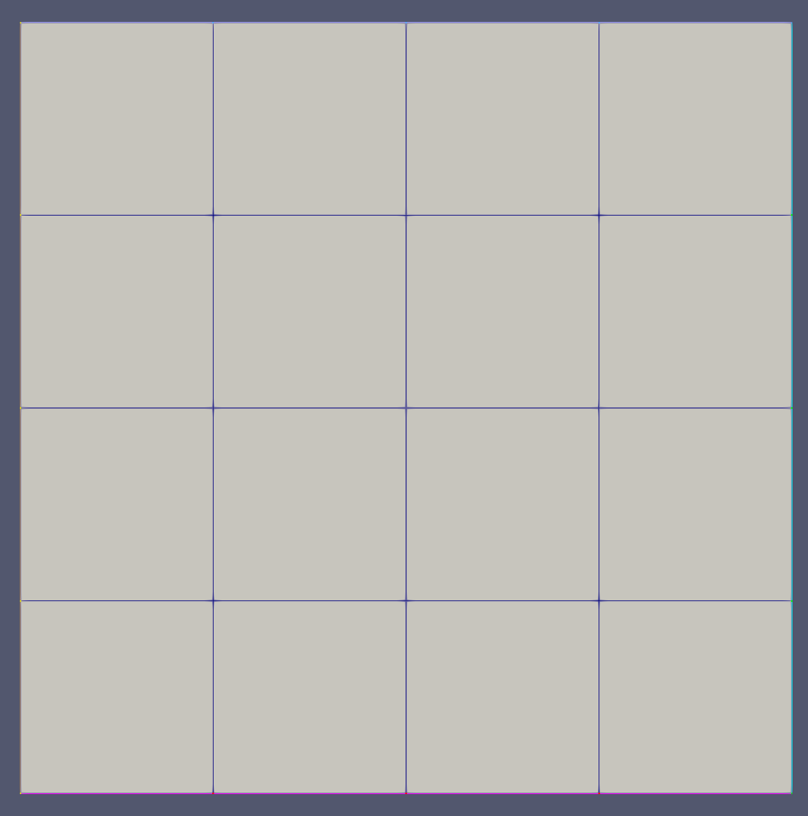
Figure 1: The simple one-block mesh to be trimmed by this mesh generator.
The simple mesh shown above can be cut by XYMeshLineCutter with CUT_ELEM_TRI method using the following input block:
[Mesh<<<{"href": "../../syntax/Mesh/index.html"}>>>]
  [mlc]
    type = XYMeshLineCutter<<<{"description": "This XYMeshLineCutter object is designed to trim the input mesh by removing all the elements on one side of a given straight line with special processing on the elements crossed by the cutting line to ensure a smooth cross-section.", "href": "XYMeshLineCutter.html"}>>>
    input<<<{"description": "The input mesh that needs to be trimmed."}>>> = ext
    cut_line_params<<<{"description": "Cutting line parameters, which are a, b, and c in line equation a*x+b*y+c=0. Note that a*x+b*y+c>0 part is being removed."}>>> = '1 -2 0'
    new_boundary_id<<<{"description": "Boundary id to be assigned to the boundary formed by the cutting."}>>> = 20
  []
[]The mesh after the line cutting using CUT_ELEM_TRI method is shown in Figure 2

Figure 2: The simple one-block mesh cut using the CUT_ELEM_TRI method.
Alternatively, the simple mesh can also be cut with the MOV_NODE method and produce the following output shown in Figure 3
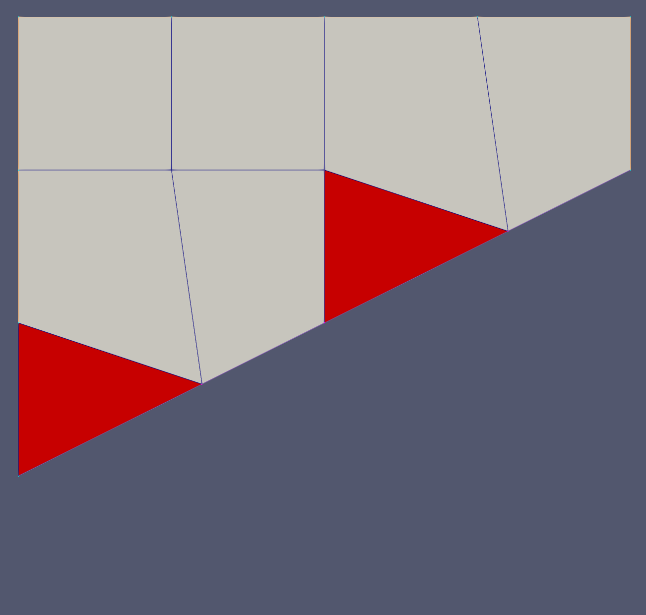
Figure 3: The simple one-block mesh cut using the MOV_NODE method.
As both methods work well, the CUT_ELEM_TRI method does produce some fine elements near the cutting line.
On the other hand, if a more complex mesh that contains multiple subdomains needs to be cut, as illustrated in Figure 4.

Figure 4: The complex multi-block mesh to be trimmed by this mesh generator.
The complex mesh shown above can be cut by XYMeshLineCutter with CUT_ELEM_TRI method using the following input block:
[Mesh<<<{"href": "../../syntax/Mesh/index.html"}>>>]
  [mlc]
    type = XYMeshLineCutter<<<{"description": "This XYMeshLineCutter object is designed to trim the input mesh by removing all the elements on one side of a given straight line with special processing on the elements crossed by the cutting line to ensure a smooth cross-section.", "href": "XYMeshLineCutter.html"}>>>
    input<<<{"description": "The input mesh that needs to be trimmed."}>>> = interface45
    cut_line_params<<<{"description": "Cutting line parameters, which are a, b, and c in line equation a*x+b*y+c=0. Note that a*x+b*y+c>0 part is being removed."}>>> = '1 -2 2'
    new_boundary_id<<<{"description": "Boundary id to be assigned to the boundary formed by the cutting."}>>> = 20
    input_mesh_external_boundary_id<<<{"description": "Boundary id of the external boundary of the input mesh."}>>> = 100
  []
[]The mesh after the line cutting using CUT_ELEM_TRI method is shown in Figure 5

Figure 5: The complex multi-block mesh cut using the CUT_ELEM_TRI method.
The fine elements issue near the cutting line can be relieved by enabling "improve_tri_elements", as shown in Figure 6.
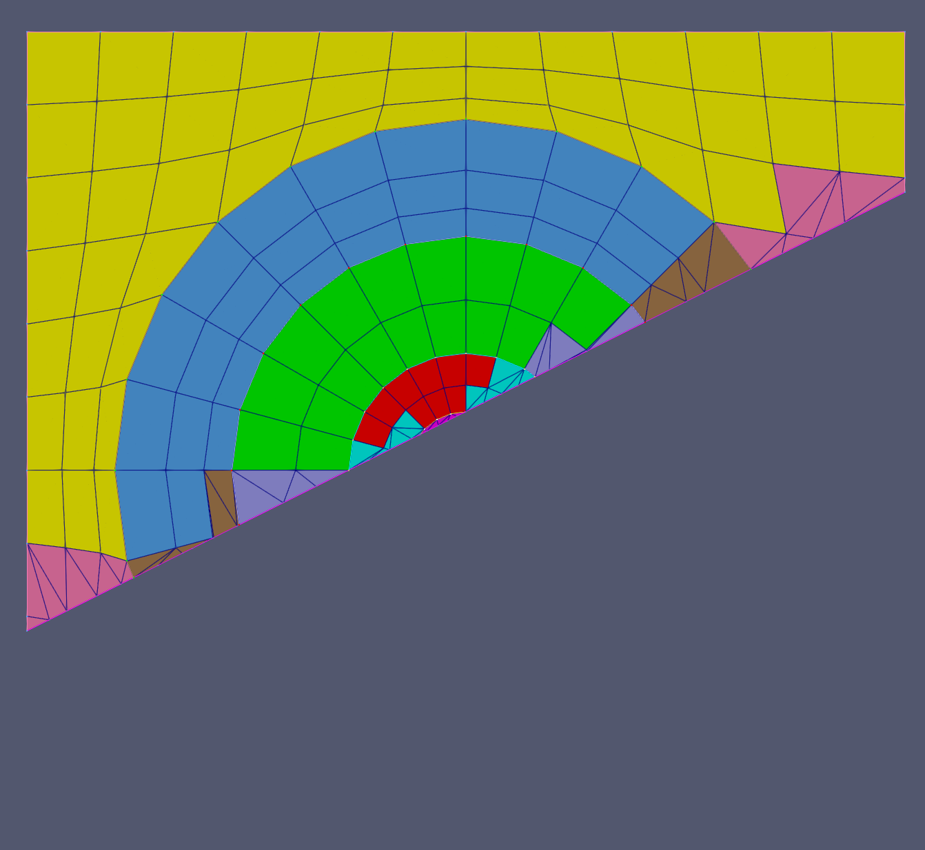
Figure 6: The complex multi-block mesh cut using the CUT_ELEM_TRI method.
Alternatively, the complex mesh can also be cut with the MOV_NODE method and produce the following output shown in Figure 7
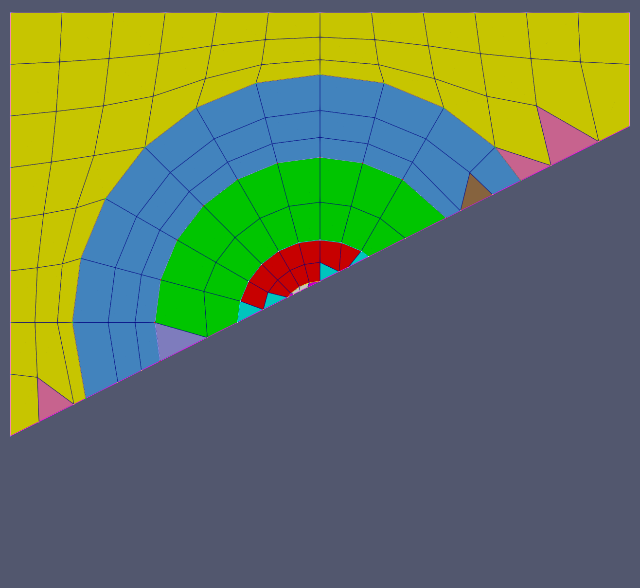
Figure 7: The complex multi-block mesh cut using the MOV_NODE method.
By comparing the output meshes produced using the two methods, it is clear that the CUT_ELEM_TRI method preserve the original shape better but creates fine TRI3 elements near the cutting line. On the other hand, the MOV_NODE method is free from the "fine elements" issue, but does skew the interface near the cutting line slightly if this interface is not symmetric near the cutting line. The skewing can be relieved by listing the interface boundary ids in "other_boundaries_to_conform", as shown in Figure 8. In summary, users should make a wise selection on the method according to their specific applications.
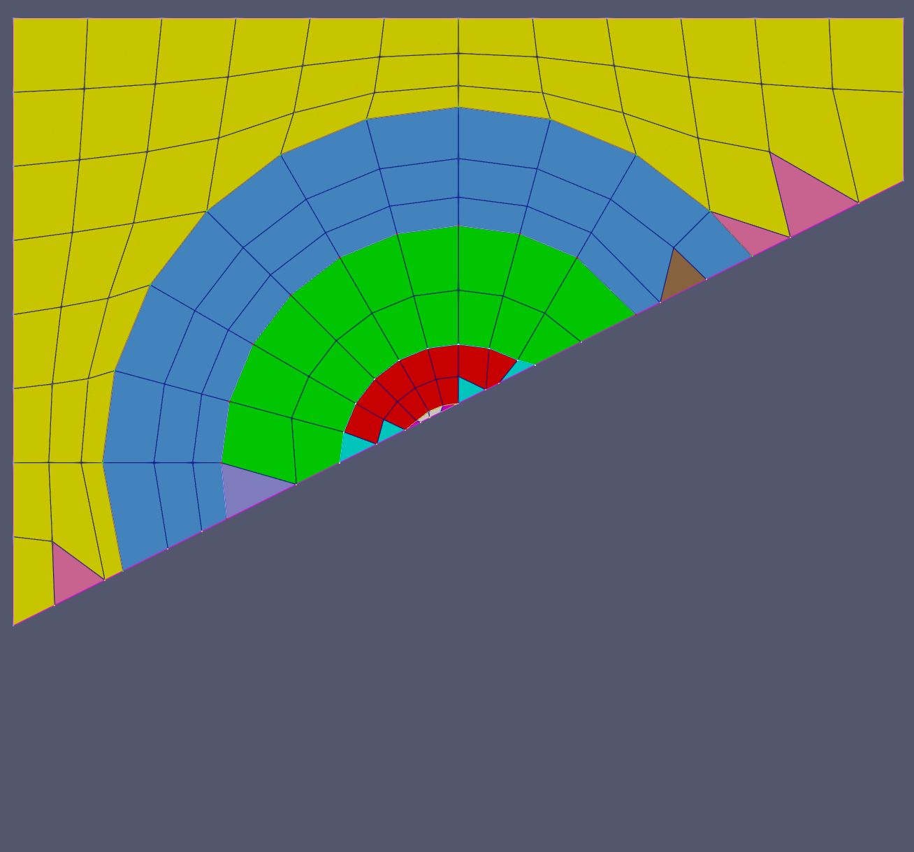
Figure 8: The complex multi-block mesh cut using the MOV_NODE method with all interfaces provided as other_boundaries_to_conform.
Input Parameters
- cutting_typeCUT_ELEM_TRIWhich method is to be used to cut the input mesh. 'CUT_ELEM_TRI' is the recommended method but it may cause fine elements near the cutting line, while 'MOV_NODE' deforms subdomain boundaries if they are not perpendicular to the cutting line.
Default:CUT_ELEM_TRI
C++ Type:MooseEnum
Controllable:No
Description:Which method is to be used to cut the input mesh. 'CUT_ELEM_TRI' is the recommended method but it may cause fine elements near the cutting line, while 'MOV_NODE' deforms subdomain boundaries if they are not perpendicular to the cutting line.
- improve_tri_elementsFalseWhether to improve TRI3 elements after CUT_ELEM_TRI method.
Default:False
C++ Type:bool
Controllable:No
Description:Whether to improve TRI3 elements after CUT_ELEM_TRI method.
- input_mesh_external_boundary_idBoundary id of the external boundary of the input mesh.
C++ Type:short
Controllable:No
Description:Boundary id of the external boundary of the input mesh.
- other_boundaries_to_conformIDs of the other boundaries that need to be conformed to during nodes moving.
C++ Type:std::vector<short>
Controllable:No
Description:IDs of the other boundaries that need to be conformed to during nodes moving.
- tri_elem_subdomain_name_suffixtrimmer_triSuffix to the block name used for quad elements that are trimmed/converted into triangular elements to avert degenerate quad elements
Default:trimmer_tri
C++ Type:SubdomainName
Controllable:No
Description:Suffix to the block name used for quad elements that are trimmed/converted into triangular elements to avert degenerate quad elements
- tri_elem_subdomain_shiftCustomized id shift to define subdomain ids of the converted triangular elements.
C++ Type:unsigned short
Controllable:No
Description:Customized id shift to define subdomain ids of the converted triangular elements.
Optional Parameters
- enableTrueSet the enabled status of the MooseObject.
Default:True
C++ Type:bool
Controllable:No
Description:Set the enabled status of the MooseObject.
- save_with_nameKeep the mesh from this mesh generator in memory with the name specified
C++ Type:std::string
Controllable:No
Description:Keep the mesh from this mesh generator in memory with the name specified
Advanced Parameters
- nemesisFalseWhether or not to output the mesh file in the nemesisformat (only if output = true)
Default:False
C++ Type:bool
Controllable:No
Description:Whether or not to output the mesh file in the nemesisformat (only if output = true)
- outputFalseWhether or not to output the mesh file after generating the mesh
Default:False
C++ Type:bool
Controllable:No
Description:Whether or not to output the mesh file after generating the mesh
- show_infoFalseWhether or not to show mesh info after generating the mesh (bounding box, element types, sidesets, nodesets, subdomains, etc)
Default:False
C++ Type:bool
Controllable:No
Description:Whether or not to show mesh info after generating the mesh (bounding box, element types, sidesets, nodesets, subdomains, etc)