- inputThe input mesh that needs to be trimmed.
C++ Type:MeshGeneratorName
Controllable:No
Description:The input mesh that needs to be trimmed.
- plane_normalThe normal vector of the plane.
C++ Type:libMesh::Point
Controllable:No
Description:The normal vector of the plane.
- plane_pointA point on the plane.
C++ Type:libMesh::Point
Controllable:No
Description:A point on the plane.
CutMeshByPlaneGenerator
This CutMeshByPlaneGenerator object is designed to trim the input mesh by removing all the elements on one side of a given plane with special processing on the elements crossed by the cutting plane to ensure a smooth cross-section. The output mesh only consists of TET4 elements.
Overview
The CutMeshByPlaneGenerator is basically the 3D version of XYMeshLineCutter. It is used to slice a 3D input mesh along a given plane, and discard the portion of the mesh on one side of the plane. The input mesh, given by "input", must be 3D and contain only first-order elements. The cutting plane is specified by "plane_normal" and "plane_point", which are two libMesh::Point type data that represent the normal vector of the cutting plane and a point on the cutting plane, respectively. This mesh generator removes the part of the mesh located on the side of the plane in the direction of the normal vector. As each element that is across the cutting plane is cut based on the interception points, this mesh generator ensures a straight cut instead of a "zigzag" cut along element boundaries as generated by PlaneDeletionGenerator.
Methods
As cutting a TET4 element along a plane is most straightforward, the elements that are crossed by the cutting plane are converted into TET4 elements before the cutting operation. The CutMeshByPlaneGenerator supports two methods for this conversion:
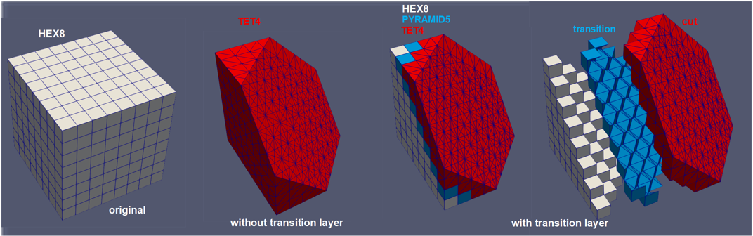
Figure 1: Example of cutting a cube mesh consisting of HEX8 elements along a plane. From left to right: (1) original mesh; (2) mesh after the cutting without the transition layer; (3) mesh after the cutting with the transition layer; (4) detailed breakdown of the mesh cut with the transition layer.
Method 1: Full Conversion to TET4 Elements
This method converts all elements of the input mesh into TET4 elements. The conversion is performed using the ElementsToTetrahedronsConverter algorithm, which splits non-TET4 elements into TET4 elements. Note that only those elements that will be fully or partially retained after the cutting are split.
As all the non-TET4 elements are converted into TET4 elements, the output mesh only contains TET4 elements. Thus, all the subdomain ids and names of the input mesh are preserved in the output mesh. See the second subfigure in Figure 1 for an example.
Method 2: Transition Layer Approach
The transition layer approach utilizes an algorithm that is similar to what is described in BoundaryElementConversionGenerator. In this method, only the elements that are crossed by the cutting plane are converted into TET4 elements (using the ElementsToTetrahedronsConverter algorithm). The elements that are adjacent to these converted TET4 elements are also converted into a combination of TET4 and PYRAMID5 elements, which are then used to create a transition layer between the TET4 elements and the original elements. In this case, the majority of elements in the input mesh can be retained as they are. This option can be enabled by setting "generate_transition_layer" to true. See the third and fourth subfigures in Figure 1 for an example.
As new types of elements are introduced in the transition layer, only the subdomain ids and names of the input mesh that are associated with the retained elements are preserved in the output mesh. The new TET4 and PYRAMID5 elements in the transition layer are assigned new subdomain names that are based on the original subdomain names with a suffix defined by "converted_pyramid_element_subdomain_name_suffix" and "converted_tet_element_subdomain_name_suffix", respectively. The new subdomain ids are assigned by automatically shifting the original ids.
Cutting of TET4 Elements along Plane
Once all the elements of the input mesh that are involved in cutting have been converted into TET4 elements, the cutting method only needs to be applied to TET4 elements. First, all the elements that are cut by the given cutting plane are identified. For the TET4 elements involved, their relationship with the cutting plane can be categorized into one of the six cases shown in Figure 2. For each of these six cases, new nodes are created at the intersection points between the cutting plane and the edges of the TET4 element. Then the red part of the original TET4 element is removed and new TET4 element(s) are created as shown in Figure 2. The cross-sections created by this cutting procedure are assigned a new boundary ID as defined by "cut_face_id"
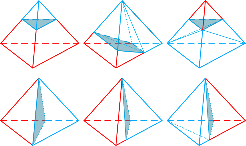
Figure 2: The six possible cases when slicing a TET element. The cutting plane intersection with the element is shown as blue faces. The red part of the original TET element is removed after cutting, while the blue part of the original TET element is kept and split into multiple TET elements if necessary.
Example Syntax
[Mesh<<<{"href": "../../syntax/Mesh/index.html"}>>>]
  [cut]
    type = CutMeshByPlaneGenerator<<<{"description": "This CutMeshByPlaneGenerator object is designed to trim the input mesh by removing all the elements on one side of a given plane with special processing on the elements crossed by the cutting plane to ensure a smooth cross-section. The output mesh only consists of TET4 elements.", "href": "CutMeshByPlaneGenerator.html"}>>>
    input<<<{"description": "The input mesh that needs to be trimmed."}>>> = block_1
    plane_point<<<{"description": "A point on the plane."}>>> = '0.5 0.5 0.3'
    plane_normal<<<{"description": "The normal vector of the plane."}>>> = '1.0 0.9 0.8'
  []
[]Input Parameters
- converted_pyramid_element_subdomain_name_suffixto_pyramidThe suffix to be added to the original subdomain name for the subdomains containing the elements converted to PYRAMID5. This is only applicable when transition layer is generated.
Default:to_pyramid
C++ Type:SubdomainName
Controllable:No
Description:The suffix to be added to the original subdomain name for the subdomains containing the elements converted to PYRAMID5. This is only applicable when transition layer is generated.
- converted_tet_element_subdomain_name_suffixto_tetThe suffix to be added to the original subdomain name for the subdomains containing the elements converted to TET4. This is only applicable when transition layer is generated.
Default:to_tet
C++ Type:SubdomainName
Controllable:No
Description:The suffix to be added to the original subdomain name for the subdomains containing the elements converted to TET4. This is only applicable when transition layer is generated.
- cut_face_idThe boundary id of the face generated by the cut. An id will be automatically assigned if not provided.
C++ Type:short
Controllable:No
Description:The boundary id of the face generated by the cut. An id will be automatically assigned if not provided.
- cut_face_nameThe boundary name of the face generated by the cut.
C++ Type:BoundaryName
Controllable:No
Description:The boundary name of the face generated by the cut.
- epsilon0Fuzzy comparison tolerance
Default:0
C++ Type:double
Unit:(no unit assumed)
Controllable:No
Description:Fuzzy comparison tolerance
- generate_transition_layerFalseWhether to generate a transition layer for the cut mesh. If false, the entire input mesh will be converted to TET4 elements to facilitate the cutting; if true, only the elements near the cut face will be converted with a transition layer to maintain compatibility with the original mesh.
Default:False
C++ Type:bool
Controllable:No
Description:Whether to generate a transition layer for the cut mesh. If false, the entire input mesh will be converted to TET4 elements to facilitate the cutting; if true, only the elements near the cut face will be converted with a transition layer to maintain compatibility with the original mesh.
Optional Parameters
- disable_fpoptimizerFalseDisable the function parser algebraic optimizer
Default:False
C++ Type:bool
Controllable:No
Description:Disable the function parser algebraic optimizer
- enable_ad_cacheTrueEnable caching of function derivatives for faster startup time
Default:True
C++ Type:bool
Controllable:No
Description:Enable caching of function derivatives for faster startup time
- enable_auto_optimizeTrueEnable automatic immediate optimization of derivatives
Default:True
C++ Type:bool
Controllable:No
Description:Enable automatic immediate optimization of derivatives
- enable_jitTrueEnable just-in-time compilation of function expressions for faster evaluation
Default:True
C++ Type:bool
Controllable:No
Description:Enable just-in-time compilation of function expressions for faster evaluation
- evalerror_behaviornanWhat to do if evaluation error occurs. Options are to pass a nan, pass a nan with a warning, throw a error, or throw an exception
Default:nan
C++ Type:MooseEnum
Controllable:No
Description:What to do if evaluation error occurs. Options are to pass a nan, pass a nan with a warning, throw a error, or throw an exception
Parsed Expression Advanced Parameters
- enableTrueSet the enabled status of the MooseObject.
Default:True
C++ Type:bool
Controllable:No
Description:Set the enabled status of the MooseObject.
- save_with_nameKeep the mesh from this mesh generator in memory with the name specified
C++ Type:std::string
Controllable:No
Description:Keep the mesh from this mesh generator in memory with the name specified
Advanced Parameters
- nemesisFalseWhether or not to output the mesh file in the nemesisformat (only if output = true)
Default:False
C++ Type:bool
Controllable:No
Description:Whether or not to output the mesh file in the nemesisformat (only if output = true)
- outputFalseWhether or not to output the mesh file after generating the mesh
Default:False
C++ Type:bool
Controllable:No
Description:Whether or not to output the mesh file after generating the mesh
- show_infoFalseWhether or not to show mesh info after generating the mesh (bounding box, element types, sidesets, nodesets, subdomains, etc)
Default:False
C++ Type:bool
Controllable:No
Description:Whether or not to show mesh info after generating the mesh (bounding box, element types, sidesets, nodesets, subdomains, etc)